
Wireless Trailer Tester
A wireless trailer tester for checking the lights on a trailer, caravan, or anything using a standard trailer socket.
Personal favourite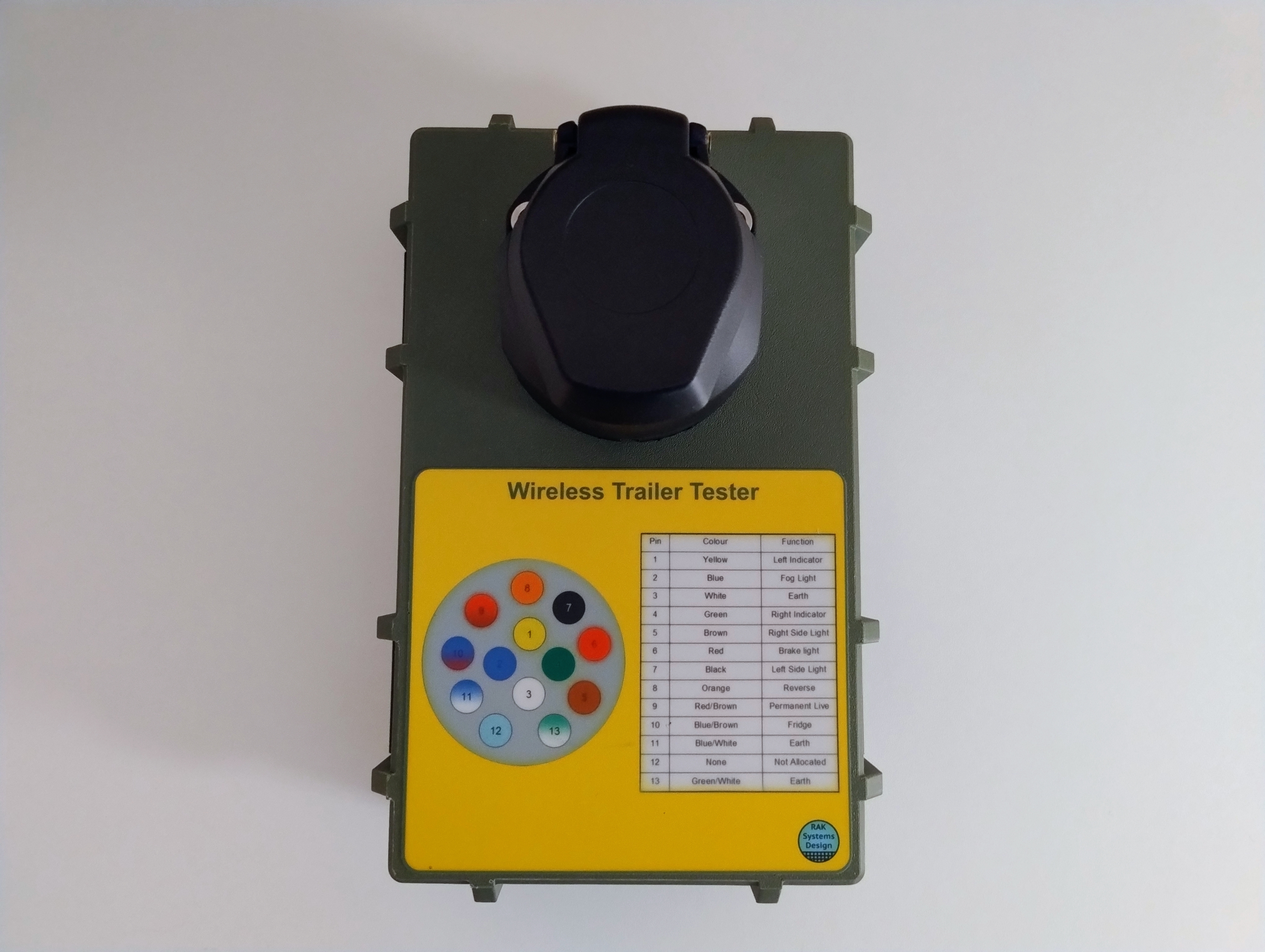
Completed tester showing front label pin designations
Video showing wireless trailer tester in use
The problem
When connecting the caravan to a new towbar, I came across issues with some of the caravan's lights not working. Testers are available to check the towbar socket, but I couldn't source a suitable tester for the caravan/trailer plug itself. Searching online, I found some DIY testers, but none of them inspired confidence — so I came up with my own solution: a fully self-contained wireless trailer tester that can run on an internal battery or an external +12V source, controlled from a mobile phone webpage. The tester uses the latest 13 pin socket, for older 7 pin sockets a standard 13 pin to 7 pin adapter can be purchased.
The tester is built from readily available electronic modules, a 3D-printed housing, and a standard trailer socket, and is easy to wire and configure. The microcontroller is an ESP8266 module with Wi-Fi built in, which lets you connect to the tester while viewing the rear lights remotely and fault-find as you go.
Parts required
- ESP8266 microcontroller module
- LM2596 voltage regulator module, set to +5V output (from +12V source)
- 8-way relay module with opto-isolator inputs — see photos for reference
- 13-pin trailer socket
- 3S LiPo battery, 1800mAh
- Pair of XT60 connectors
- Terminal block
- 2 x Velcro straps
- 3 x M6 x 35mm Allen bolts for mounting the trailer socket
- 3 x M6 nuts and washers for mounting the trailer socket
- 10 x M2.5 x 6mm screws for mounting the modules
- 3D-printed housing and custom instruction labels
Design & CAD
The housing was designed in Fusion 360 — note that I used a parametric design originally sourced from the Printables website, but the page is no longer available, so I'm unable to credit the original author. The labels were produced using Silhouette Studio and cut on a Portrait 3 cutter. The code can be easily changed to alter the network and password that suits best, as can the name at the bottom of the screen.


The webpage is a simple HTML page stored within the ESP8266's own code. The IP address is fixed at 192.168.2.1, and the network is configured as "Trailer_Tester" with the password "Trailer".
Note that when connecting to the network using a mobile phone, you must turn off mobile data.
Once connected, open a browser on the phone and enter the IP address above — this should show the webpage as in the photos below.


Fabrication
The build covers 3D printing the housing components, wiring the modules and socket, and printing the labels.
3D printing
Print the parts in PLA, PETG, or ASA, with 4 perimeters and 40% infill — no supports required. The hinges use standard 1.7mm filament as a pivot pin.
Labels
Print the labels on vinyl matte self-adhesive inkjet paper, then cover with clear self-adhesive matte vinyl to waterproof them, then cut.


Wiring
Straightforward throughout — use crimps and heat shrink on every joint. Refer to the photos above for reference.
Power & ground
- +12V: Input terminal block to LM2596 IN+
- Gnd: Input terminal block to LM2596 IN−, LM2596 OUT− to ESP8266 Gnd, ESP8266 Gnd to relay board Gnd (pin 1) to trailer socket pin 3
- +5V: LM2596 OUT+ to ESP8266 pin Vin to relay board JD-Vcc pin (remove jumper)
- +3.3V: ESP8266 pin 3.3 to relay board Vcc (pin 10) — opto-isolator supply
ESP8266 connections
- Left: ESP8266 pin D5 to relay board IN1
- Right: ESP8266 pin D6 to relay board IN2
- Brake: ESP8266 pin D7 to relay board IN3
- Side: ESP8266 pin D8 to relay board IN4
- Fog: ESP8266 pin Rx to relay board IN5
- Reverse: ESP8266 pin Tx to relay board IN6
Relay board outputs
- +12V common: Input terminal block to K1 common to K2 common to K3 common to K4 common to K5 common to K6 common
- K1 normally-open contact to trailer socket pin 1
- K2 normally-open contact to trailer socket pin 4
- K3 normally-open contact to trailer socket pin 6
- K4 normally-open contact to trailer socket pin 5, looped to pin 7
- K5 normally-open contact to trailer socket pin 2
- K6 normally-open contact to trailer socket pin 8

Top — STL file
Drag to rotate · Scroll to zoom
Top (alternative) — STL file
Drag to rotate · Scroll to zoom
Bottom — STL file
Drag to rotate · Scroll to zoom
Hinge — STL file
Drag to rotate · Scroll to zoom
Clasp — STL file
Drag to rotate · Scroll to zoom
Pin — STL file
Drag to rotate · Scroll to zoom
Seal — STL file
Drag to rotate · Scroll to zoom
Battery plate — STL file
Drag to rotate · Scroll to zoom
Trailer_Tester — ZIP file
Front decal — Studio3 file
Front decal cut file — Studio3 file
Rear decal — Studio3 file
Rear decal cut file — Studio3 file